Students can Download Tamil Nadu 12th Physics Model Question Paper 1 English Medium Pdf, Tamil Nadu 12th Physics Model Question Papers helps you to revise the complete Tamilnadu State Board New Syllabus and score more marks in your examinations.
TN State Board 12th Physics Model Question Paper 1 English Medium
Instructions:
- The question paper comprises of four parts
- You are to attempt all the parts. An internal choice of questions is provided wherever: applicable
- All questions of Part I, II, III and IV are to be attempted separately
- Question numbers 1 to 15 in Part I are Multiple choice Questions of one mark each. These are to be answered by choosing the most suitable answer from the given four alternatives and writing the option code and the corresponding answer
- Question numbers 16 to 24 in Part II are two-mark questions. These are lo be answered in about one or two sentences.
- Question numbers 25 to 33 in Part III are three-mark questions. These are lo be answered in about three to five short sentences.
- Question numbers 34 to 38 in Part IV are five-mark questions. These are lo be answered in detail. Draw diagrams wherever necessary.
Time: 3 Hours
Max Marks: 70
PART – 1
Answer all the questions. Choose the correct answer. [15 × 1 = 15]
Question 1.
An electric dipole is placed at an alignment angle of 30° with an electric field of 2 × 10⁵ NC-1. It experiences a torque equal to 8 N m. The charge on the dipole if the dipole length is 1 cm is ……………….
(a) 4 mC
(b) 8 mC
(c) 5 mC
(d) 7 mC
Answer:
(b) 8 mC
Question 2.
Dielectric constant of metals is
(a) 1
(b) greater then 1
(c) zero
(d) infinite
Answer:
(d) infinite
![]()
Question 3.
Two wires of A and B with circular cross section made up of the same material with equal lengths. Suppose RA = 3 RB, then what is the ratio of radius of wire A to that of B?
(a) 3
(b) √3
(c) \(\frac{1}{\sqrt{3}}\)
(d) \(\frac{1}{3}\)
Answer:
(c) \(\frac{1}{\sqrt{3}}\)
Question 4.
A circular coil of radius 5 cm and 50 turns carries a current of 3 ampere. The magnetic dipole moment of the coil is
(a) 1.0 amp – m2
(b) 1.2 amp – m2
(c) 0.5 amp – m2
(d) 0.8 amp – m2
Answer:
(b) 1.2 amp – m2
Question 5.
A straight conductor carrying a current I, is split into a circular loop of radius r as shown in the figure. The magnetic field at the centre O of the circle, in tesla is …………..

(a) \(\frac{\propto_{0} \mathrm{I}}{2 r}\)
(b) \(\frac{\mu_{0} I}{2 \pi r}\)
(c) \(\frac{\mu_{0} I}{\pi r}\)
(d) zero
Hint Field due to the upper and lower semicircles will cancel out.
Answer:
(d) zero
Question 6.
The flux linked with a coil at any instant t is given by ΦB = 10t2 – 50t + 250. The induced emf at t = 3s is ………………. .
(a) -190 V
(b) -10 V
(c) 10 V
(d) 190 V
Answer:
(b) -10 V
Question 7.
Quantity that remains unchanged in a transformer is
(a) voltage
(b) current
(c) frequency
(d) none of these
Answer:
(c) frequency
![]()
Question 8.
The electric and the magnetic field, associated with an electromagnetic wave, propagating along X axis can be represented by
(a) \(\overrightarrow{\mathrm{E}}\) = E0ĵ and \(\overrightarrow{\mathrm{B}}\) = B0K̂
(b) \(\overrightarrow{\mathrm{E}}\) = E0K̂ and \(\overrightarrow{\mathrm{B}}\) = B0ĵ
(c) \(\overrightarrow{\mathrm{E}}\) = E0î and \(\overrightarrow{\mathrm{B}}\) = B0ĵ
(d) \(\overrightarrow{\mathrm{E}}\) = E0ĵ and \(\overrightarrow{\mathrm{B}}\) = B0ĵ
Answer:
(b) \(\overrightarrow{\mathrm{E}}\) = E0K̂ and \(\overrightarrow{\mathrm{B}}\) = B0ĵ
Question 9.
A ray of light strikes a glass plate at an angle 60°. If the reflected and refracted rays are perpendicular to each other, the refractive index of the glass is
(a) √3
(b) \(\frac{3}{2}\)
(c) \(\sqrt{\frac{3}{2}}\)
(d) 2
Hint. Angle of refraction r = 60° ;
Angle of incident i = 30°
sin i = n × sin r
n = \(\frac{\sin 30^{\circ}}{\sin 60^{\circ}}\) = √3
Answer:
(a) √3
Question 10.
For light incident from air onto a slab of refractive index 2. Maximum possible angle of refraction is
(a) 30°
(b) 45°
(c) 60°
(d) 90°
Hint. From Snell’s law, µ = \(\frac{\sin i}{\sin r}\)
Now consider an angle of incident is 90°
sinr = \(\frac{\sin 90^{\circ}}{2}\)
r = sin-1 (0.5)
r = 30°
Answer:
(a) 30°
Question 11.
A light of wavelength 500 nm is incident on a sensitive plate of photoelectric work function 1.235 eV. The kinetic energy of the photo electrons emitted is be (Take h = 6.6 × 10⁻³⁴ Js)
(a) 0.58 eV
(b) 2.48 eV
(c) 1.24 eV
(d) 1.16 eV
Hint.
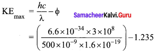
= (2.48 – 1.235) eV= 1.245 eV
Answer:
(c) 1.24 eV
![]()
Question 12.
In a hydrogen atom, the electron revolving in the fourth orbit, has angular momentum equal to ………….. .
(a) h
(b) \(\frac{h}{\pi}\)
(c) \(\frac{4 h}{\pi}\)
(d) \(\frac{2 h}{\pi}\)
Hint Angular momentum of an electron is an integral multiple of \(\frac{h}{2 \pi}\)
According to Bohr atom model,
Angular momentum of an electron mvr = \(\frac{nh}{2 \pi}\)
n = 4th orbit = \(\frac{4h}{2 \pi}\)
mvr = \(\frac{2 h}{\pi}\)
Answer:
(d) \(\frac{2 h}{\pi}\)
Question 13.
The barrier potential of a silicon diode is approximately
(a) 0.7 V
(b) 0.3V
(c) 2.0 V
(d) 2.2V
Answer:
(a) 0.7 V
Question 14.
The signal is affected by noise in a communication system
(a) At the transmitter
(b) At the modulator
(c) In the channel
(d) At the receiver
Answer:
(c) In the channel
Question 15.
The particle which gives mass to protons and neutrons are
(a) Higgs particle
(b) Einstein particle
(c) Nanoparticle
(d) Bulk particle
Answer:
(a) Higgs particle
PART – II
Answer any six questions. Question No. 21 is compulsory. [6 × 2 = 12]
Question 16.
Define ‘electrostatic potential”.
Answer:
The electric potential at a point P is equal to the work done by an external force to bring a unit positive charge with constant velocity from infinity to the point P in the region of the external electric field \(\overrightarrow{\mathrm{E}} \cdot\)
Question 17.
Define temperature coefficient of resistance.
Answer:
It is defined as the ratio of increase in resistivity per degree rise in temperature to its resistivity at T0
∴ \(\alpha=\frac{\rho_{\mathrm{T}}-\rho_{\mathrm{o}}}{\rho_{\mathrm{o}}\left(\mathrm{T}-\mathrm{T}_{\mathrm{o}}\right)}=\frac{\Delta \rho}{\rho_{\mathrm{o}} \Delta \mathrm{T}}\)
![]()
Question 18.
The self-inductance of an air-core solenoid is 4.8 mH. If its core is replaced by iron core, then its self-inductance becomes 1.8 H. Find out the relative permeability of iron.
Answer:
Lair = 4.8 × 10⁻³
Liron = 1.8 H
Lair = μ0n2Al = 4.8 × 10″3H
Liron = μn2Al = μ0μr n2Al= 1.8 H
∴ \(\mu_{r}=\frac{L_{\text {ipon }}}{L_{\text {air }}}=\frac{1.8}{4.8 \times 10^{-3}}=375\)
Question 19.
What is meant by Fraunhofer lines?
Answer:
When the spectrum obtained from the Sun is examined, it consists of large number of dark lines (line absorption spectrum). These dark lines in the solar spectrum are known as Fraunhofer lines.
Question 20.
What is power of a lens?
Answer:
The power of a lens P is defined as the reciprocal of its focal length. P = \(\frac{1}{f}\)
The unit of power is diopter D.
Question 21.
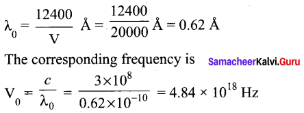
Calculate the cut-off wavelength and cutoff frequency of x-rays from an x-ray tube of accelerating potential 20,000 V.
Answer:
The cut-off wavelength of the characteristic x-rays is
Question 22.
What is mass defect?
Answer:
The mass of any nucleus is always less than the sum of the mass of its individual constituents. The difference in mass Am is called mass defect.
Δm = (Zmp + Nmn) – M
Question 23.
Simplify the Boolean identity AC + ABC = AC
Answer:
Step 1: AC (1 + B) = AC.1 [OR law-2]
Step 2: AC . 1 = AC [AND law 2]
Therefore, AC + ABC = AC
Circuit Description
Thus the given statement is proved.

![]()
Question 24.
What do you mean by Internet of Things?
Answer:
Internet of Things (IoT), it is made possible to control various devices from a single device. Example: home automation using a mobile phone.
PART-III
Answer any six questions. Question No. 26 is compulsory. [6 × 3 = 18]
Question 25.
Give the relation between electric field and electric potential.
Answer:
Consider a positive charge q kept fixed at the origin. To move a unit positive charge by a small ‘ distance dx in the electric field E, the work done is given by dW = -E dx. The minus sign implies that work is done against the electric field. This work done is equal to electric potential difference. Therefore,
dW = dV. (or) dV = -E dx
Hence E = \(-\frac{d V}{d x}\)
The electric field is the negative gradient of the electric potential.
Question 26.
A cicopper wire of 10”6 m2 area of cross section, carries a current of 2 A. If the number of electrons per cubic meter is 8 × 1028, calculate the current density and average drift velocity
Answer:
Cross-sections area of copper wire, A = 10-6 m2
I = 2A
Number of electron, n = 8 × 1028
Current density, J = \(\frac{I}{A}=\frac{2}{10^{-6}}\)
J = 2 × 10⁶Am-2
Average drift velocity, Vd = \(\frac{I}{n e A}\)
e is the charge of electron = 1.6 × 10⁻⁹ C

Vd = 0.15625 × 10⁻³ ; Vd = 15.6 × 10⁻⁵ ms-1
Question 27.
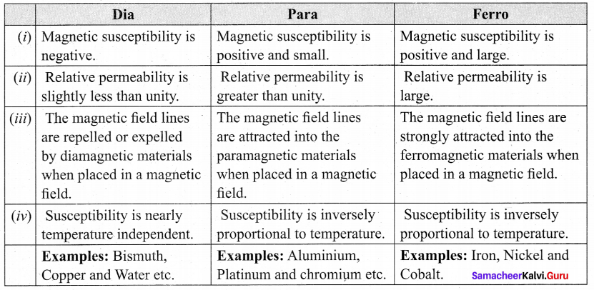
compare dia, para and ferromagnetism.
Answer:
Question 28.
State Faraday’s laws of electromagnetic induction.
Answer:
First law: Whenever magnetic flux linked with a closed circuit changes, an emf is induced in the circuit.
Second law: The magnitude of induced emf in a closed circuit is equal to the time rate of change of magnetic flux linked with the circuit.
Question 29.
Why does sky appear blue?
Answer:
Blue colour of the sky is due to scattering of sunlight by air molecules. According to Rayleigh’s law, intensity of scattered light, I ∝ \(\frac{1}{\lambda^{4}}\). So blue light of shorter wavelength is scattered much more than red light of larger wavelength. The blue component is proportionally more in light coming from different parts of the sky. That is why the sky appears blue.
![]()
Question 30.
Write down the postulates of Bohr atom model.
Answer:
Postulates of Bohr atom model:
The electron in an atom moves around nucleus in circular orbits under the influence of Coulomb electrostatic force of attraction. This Coulomb force gives necessary centripetal force for the electron to undergo circular motion.
Electrons in an atom revolve around the nucleus only in certain discrete orbits called stationary orbits where it does not radiate electromagnetic energy. Only those discrete orbits allowed are stable orbits.
Question 31.
State De Morgan’s first and second theorems.
Answer:
De Morgan’s First Theorem:
The first theorem states that the complement of the sum of two logical inputs is equal to the product of its complements.
\(\overline{\mathrm{A}+\mathrm{B}}=\overline{\mathrm{A}} \cdot \overline{\mathrm{B}}\)
De Morgan’s Second Theorem:
The second theorem states that the complement of the product of two inputs is equal to the sum of its complements.
\(\overline{\mathrm{A} \cdot \mathrm{B}}=\overline{\mathrm{A}}+\overline{\mathrm{B}}\)
Question 32.
Write down the advantages and limitations of amplitude modulation (AM).
Answer:
Advantages of AM
- Easy transmission and reception
- Lesser bandwidth requirements
- Low cost
Limitations of AM
- Noise level is high
- Low efficiency
- Small operating range
Question 33.
What are black holes?
Answer:
Black holes are end stage of stars which are highly dense massive object. Its mass ranges from 20 times mass of the sun to 1 million times mass of the sun. It has very strong gravitational force such that no particle or even light can escape from it. The existence of black holes is studied when the stars orbiting the black hole behave differently from the other starts. Every galaxy has black hole at its center. Sagittarius A* is the black hole at the center of the Milky Way galaxy.
![]()
PART – IV
Answer all the questions. [5 × 5 = 25]
Question 34.
(a) Derive an expression for the torque experienced by a dipole due to a uniform electric field.
Answer:
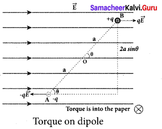
Torque experienced by an electric dipole in the uniform electric field: Consider an electric dipole of dipole moment \(\overrightarrow{\mathrm{P}}\) placed in a uniform electric field \(\overrightarrow{\mathrm{E}}\) whose field lines are equally spaced and point in the same direction. The charge +q will experience a force q \(\overrightarrow{\mathrm{E}}\) in the direction of the field and charge -q will experience a force -q \(\overrightarrow{\mathrm{E}}\) in a direction opposite to the field. Since the external field
\(\overrightarrow{\mathrm{E}}\) is uniform, the total force acting on the dipole is zero. These two forces acting at different points will constitute a couple and the dipole experience a torque. This torque tends to rotate the dipole. (Note that electric field lines of a uniform field are equally spaced and point in the same direction). The total torque on the dipole about the point O
\(\vec{\tau}=\overrightarrow{O A} \times(-q \vec{E})+\overrightarrow{O B} \times q \vec{E}\)
Using right-hand corkscrew rule, it is found that total torque is perpendicular to the plane of the paper and is directed into it.
The magnitude of the total torque
\(\vec{\tau}=|\overrightarrow{\mathrm{OA}}|(-q \overrightarrow{\mathrm{E}}) \sin \theta+|\overrightarrow{\mathrm{OB}} \| q \overrightarrow{\mathrm{E}}| \sin \theta\)
\(\vec{\tau}\) = qE 2a sin θ
where θ is the angle made by \(\vec{p}\) with \(\vec{E}\). Since p = 2aq, the torque is written in terms of the vector product as
\(\vec{\tau}=\vec{p} \times \vec{E}\)
The magnitude of this torque is \(\tau\) =pE sin θ and is maximum when θ = 90°.
This torque tends to rotate the dipole and align it with the electric field \(\vec{E}\) . Once \(\vec{p}\) is aligned with \(\vec{E}\), the total torque on the dipole becomes zero.
OR
Question 34.
(b) Explain the determination of the internal resistance of a cell using voltmeter.
Answer:
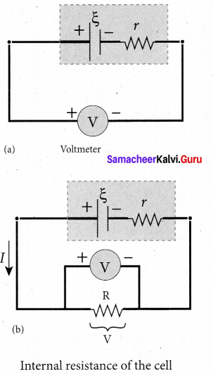
Determination of internal resistance : The emf of cell \(\xi\) is measured by connecting a high resistance voltmeter across it without connecting the external resistance R. Since the voltmeter draws very little current for deflection, the circuit may be considered as open. Hence, the voltmeter reading gives the emf of the cell. Then, external resistance R is included in the circuit and current I is established in the circuit. The potential difference across R is equal to the potential difference across the cell (V).
The potential drop across the resistor R is
V = IR …………. (1)
Due to internal resistance r of the cell, the voltmeter reads a value V, which is less than the emf of cell . It is because, certain amount of voltage (Ir) has dropped across the internal resistance r.
Then V = \(\xi\) – Ir
Ir = \(\xi\) – V
Dividing equation (2) by equation (1). we get
\(\begin{aligned}
\frac{I r}{I R} &=\frac{\xi-V}{V} \\
r &=\left|\frac{\xi-V}{V}\right| R
\end{aligned}\)
Since \(\xi\), V and R are known, internal resistance r can be determined.
![]()
Question 35.
(a) Obtain the magnetic induction at a point on the equatorial line of a bar magnet.
Answer:
Magnetic field at a point along the equatorial line due to a magnetic dipole (bar magnet) Consider a bar magnet NS. Let N be the north pole and S be the south pole of the bar magnet, each with pole strength qm and separated by a distance of 2l. The magnetic field at a point C (lies along the equatorial line) at a distance r from the geometrical center O of the bar magnet can be computed by keeping unit north pole (qm C = 1 A m) at C. The force experienced by the unit north pole at C due to pole strength N – S can be computed using Coulomb’s law of
magnetism as follows:
The force of repulsion between North Pole of the bar magnet and unit north pole at point C
(in free space) is
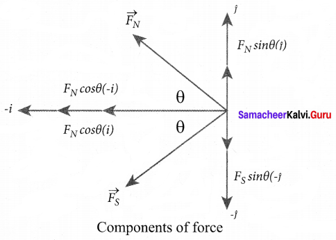
\(\overrightarrow{\mathrm{F}}_{\mathrm{N}}=-\mathrm{F}_{\mathrm{N}} \cos \theta \hat{i}+\mathrm{F}_{\mathrm{N}} \sin \theta \hat{j}\) ……….. (2)
Where FN = \(\frac{\mu_{0}}{4 \pi} \frac{q_{m}}{r^{\prime 2}}\)
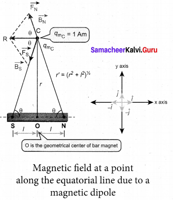
From equation (1) and equation (2). the net force at point C is \(\overrightarrow{\mathrm{F}}=\overrightarrow{\mathrm{F}}_{\mathrm{N}}+\mathrm{F}_{\mathrm{S}}\) This net force is equal to the magnetic field at the point C.
\(\overrightarrow{\mathrm{B}}\) =—(FN+Fs)cosOi
Since, FN = Fs

In a right angle triangle NOC as shown in the Figure 1

Substituting equation 4 in equation 3 we get

Since, magnitude of magnetic dipole moment is |\(\vec{p}\)m| = Pm = qm.2l and substituting in equation (5), the magnetic field at a point C

If the distance between two poles in a bar magnet are small (looks like short magnet) when compared to the distance between geometrical center O of bar magnet and the location of point
C i.e., r >>l, then,
(r2 + l2)3/2 ≈ r3 …….. (7)
Therefore, using equation (7) in equation (6), we get

Since Pmî = \(\vec{p}\) m in general, the magnetic field al equatorial point is given by

Note that magnitude of Baxial is twice that of magnitude of Bequatorial and the direction of Baxial and Bequatorial are opposite.
[OR]
![]()
Question 35.
(b) How will you induce an emf by changing the area enclosed by the coil?
Answer:
Induction of emf by changing the area of the coil: Consider a conducting rod of length 1 moving with a velocity v towards left on a rectangular metallic framework. The whole arrangement is placed in a uniform magnetic field B whose magnetic lines are perpendicularly directed into the plane of the paper. As the rod moves from AB to DC in a time dt , the area enclosed by the loop and hence the magnetic flux through the loop decreases.
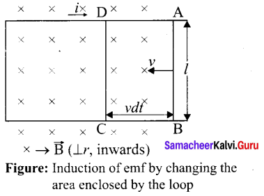
The change in magnetic flux in time dr is
dΦB = B × change in area
= B × AreaABCD
= Blvdt
since Area ABCD l(vdt)
or = \(\frac{d \Phi_{\mathrm{B}}}{d t}=\mathrm{B} l v\)
As a result of change in flux, an emf is generated in the loop. The magnitude of the induced emf is
\(\varepsilon=\frac{d \Phi_{\mathrm{B}}}{d t}=\mathrm{B} / v\)
This emf is called motional emf. The direction of induced current is found to be clockwise from Fleming’s right hand rule.
Question 36.
(a) Write down Maxwell equations in integral form.
Answer:
Maxwell’s equations in integral form: Electrodynamics can be summarized into four basic equations, known as Maxwell’s equations. These equations are analogous to Newton’s equations in mechanics. Maxwell’s equations completely explain the behaviour of charges, currents and prop
1. First equation is nothing but the Gauss’s law. It relates the net electric flux to net electric charge enclosed in a surface. Mathematically, it is expressed as
\(\oint \overrightarrow{\mathrm{E}} \cdot d \overrightarrow{\mathrm{A}}=\frac{\mathrm{Q}_{\text {enclosed }}}{\varepsilon_{0}}\)
Where \(\overrightarrow{\mathrm{E}}\) is the electric field and Qenclosed is the charge enclosed. This equation is true for both discrete or continuous distribution of charges. It also indicates that the electric field lines start from positive charge and terminate at negative charge. This implies that the electric field lines do not form a continuous closed path. In other words, it means that isolated positive charge or negative charge can exist.
2. Second equation has no name. But this law is similar to Gauss’s law in electrostatics. So this law can also be called as Gauss’s law in magnetism. The surface integral of ‘ magnetic field over a closed surface is zero. Mathematically,
\(\oint \overrightarrow{\mathrm{B}} \cdot d \overrightarrow{\mathrm{A}}=0\)
where \(\overrightarrow{\mathrm{B}}\) is the magnetic field. This equation implies that the magnetic lines of force form a continuous closed path. In other words, it means that no isolated magnetic monopole exists.
3. Third equation is Faraday’s law of electromagnetic induction. This law relates electric field with the changing magnetic flux which is mathematically written as
\(\oint \overrightarrow{\mathrm{E}} \cdot d \vec{l}=\frac{d}{d t} \Phi_{\mathrm{B}}\)
where \(\overrightarrow{\mathrm{E}}\) is the electric field. This equation implies that the line integral of the electric field around any closed path is equal to the rate of change of magnetic flux through the closed path bounded by the surface.
4. Fourth equation is modified Ampere’s circuital law. This is also known as ampere Maxwell’s law. This law relates the magnetic field around any closed path to the conduction current and displacement current through that path.
\(\oint \overrightarrow{\mathrm{B}} \cdot d \vec{l}=\mu_{0} \mathrm{I}_{\text {enclosed }}+\mu_{0} \varepsilon_{0} \int \overrightarrow{\mathrm{E}} \cdot \overrightarrow{d \mathrm{A}}\)
Where \(\overrightarrow{\mathrm{B}}\) is the magnetic field. This equation shows that both conduction and also displacement current produces magnetic field. These four equations are known as Maxwell’s equations in electrodynamics.
![]()
[OR]
Question 36.
(b) Obtain lens maker’s formula and mention its significance.
Answer:
Lens maker’s formula and lens equation: Let us consider a thin lens made up of a medium of refractive index n2 is placed in a medium of refractive index n1 . Let R1 and R2 be the radii of curvature of two spherical surfaces (1) and (2) respectively and P be the pole. Consider a point object O on the principal axis. The ray which falls very close to P, after refraction at the surface (1) forms image at I’. Before it does so, it is again refracted by the surface (2). Therefore the final image is formed at I. The general equation for the refraction at a spherical surface is given by

For the refracting surface (1), the light goes from to n1 to n2
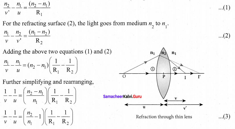
If the object is at infinity, the image is formed at the focus of the lens. Thus, for u = oo, v =/ Then the equation becomes.

If the refractive index of the lens is n2 and it is placed in air, then n2 = n and n1 = 1. So the equation (4) becomes,
\(\frac{1}{f}=(n-1)\left(\frac{1}{\mathrm{R}_{1}}-\frac{1}{\mathrm{R}_{2}}\right)\)
The above equation is called the lens maker’s formula, because it tells the lens manufactures what curvature is needed to make a lens of desired focal length with a material of particular refractive index. This formula holds good also for a concave lens. By comparing the equations (3) and (4) we can write,
\(\frac{1}{v}-\frac{1}{u}=\frac{1}{f}\) ……… (6)
This equation is known as lens equation which relates the object distance it and image distance v with the focal length / of the lens. This formula holds good for a any type of lens.
![]()
Question 37.
(a) Briefly discuss the observations of Hertz, Hallwachs and Lenard.
Answer:
Hertz observation:
- In 1887, Heinrich Hertz first became successful in generating and detecting electromagnetic wave with his high voltage induction coil to cause a spark discharge between two metallic spheres.
- When a spark is formed, the charges will oscillate back and forth rapidly and the electromagnetic waves are produced.
- The electromagnetic waves thus produced were detected by a detector that has a copper wire bent in the shape of a circle. Although the detection of waves is successful, there is a problem in observing the tiny spark produced in the detector.
- In order to improve the visibility of the spark, Hertz made many attempts and finally noticed an important thing that small detector spark became more vigorous when it was exposed to ultraviolet light.
- The reason for this behaviour of the spark was not known at that time. Later it was found that it is due to the photoelectric emission.
- Whenever ultraviolet light is incident on the metallic sphere, the electrons on the outer surface are emitted which caused the spark to be more vigorous.
Hallwachs’ observation:
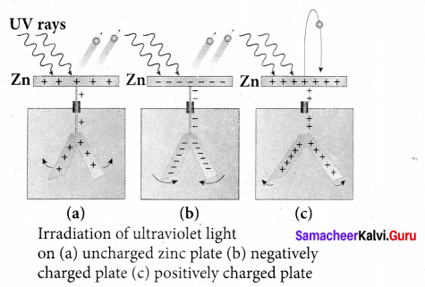
- In 1888, Wilhelm Hallwachs, a German physicist, confirmed that the strange behaviour of the spark is due to the action of ultraviolet light with his simple experiment.
- A clean circular plate of zinc is mounted on an insulating stand and is attached to a gold leaf electroscope by a wire. When the uncharged zinc plate is irradiated by ultraviolet light from an arc lamp, it becomes positively charged and the leaves will open.
- Further, if the negatively charged zinc plate is exposed to ultraviolet light, the leaves will close as the charges leaked away quickly. If the plate is positively charged, it becomes more positive upon UV rays irradiation and the leaves will open further.
- From these observations, it was concluded that negatively charged electrons were emitted from the zinc plate under the action of ultraviolet light.
Lenard,s observation:
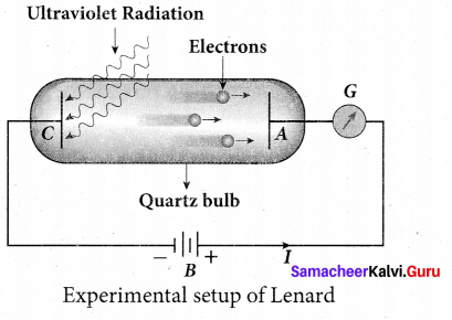
1. In 1902, Lenard studied this electron emission phenomenon in detail. The apparatus consists of two metallic plates A and C placed in an evacuated quartz bulb. The galvanometer G and battery B are connected in the circuit.
2. When ultraviolet light is incident on the negative plate C, an electric current flows in the circuit that is indicated by the deflection in the galvanorneter. On other hand, if the positive plate is irradiated by
the ultraviolet light, no current is observed in the circuit.
3. From these observations, it is concluded that when ultraviolet light falls on the negative plate. electrons are ejected from it which are attracted by the positive plate A. On reaching the positive plate through the evacuated bulb, the circuit is completed and the current flows in it.
4. Thus, the ultraviolet light falling on the negative plate causes the electron emission from
the surface of the plate.
![]()
[OR]
Question 37.
(b) Obtain the law of radioactivity.
Law of radioactive decay:
At any instant t, the number of decays per unit time, called rate of decay \(\left(\frac{d \mathrm{N}}{d t}\right)\) is proportional to the number of nuclei (N ) at the same instant.
\(\frac{d \mathrm{N}}{d t} \propto \mathrm{N}\)
By introducing a proportionality constant, the relation can be written as dN
\(\frac{d \mathrm{N}}{d t}=-\lambda \mathrm{N}\) ……… (1)
Here proportionality constant X is called decay constant which is different for different radioactive sample and the negative sign in the equation implies that the N is decreasing with time. By rewriting the equation (1), we get
dN = -λ Ndt …………(2)
Here dN represents the number of nuclei decaying in the time interval dt. Let us assume that at time t = 0 s, the number of nuclei present in the radioactive sample is N0 . By integrating the equation (2), we can calculate the number of undecayed nuclei N at any time t.
From equation (2), we get
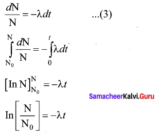
Taking exponentials on both sides, we get
N = N0e-λt …… (4)
[Note: elnx = ey ⇒ x = ey]
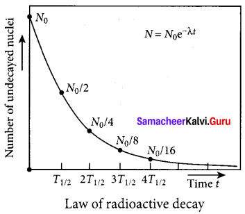
Equation (4) is called the law of radioactive decay. Here N denotes the number of undecayed nuclei present at any time t and N0 denotes the number of nuclei at initial time I = O. Note that the number of atoms is decreasing exponentially over the time. This implies that the time taken for all the radioactive nuclei to decay will be infinite. Equation (4) is plotted.
We can also define another useful quantity called activity (R) or decay rate which is the number of nuclei decayed per second and it is denoted as R = \(\left|\frac{d \mathbf{N}}{d t}\right|\)
Note: that activity R is a positive quantity. From equation (4), we get
R = \(\left|\frac{d \mathrm{N}}{d t}\right|=\lambda \mathrm{N}_{0} e^{-\lambda t}\) …… (5)
R = R0e-λt …………..(6)
where R0 = λN0
The equation (6) is also equivalent to radioactive law of decay. Here RQ is the activity of the sample at t = 0 and R is the activity of the sample at any time t. From equation (6), activity also shows exponential decay behavior. The activity R also can be expressed in terms of number of undecayed atoms present at any time t. From equation (6), since N = N0 e-λt we write
R = λN …………..(7)
Equation (4) implies that the activity at any time t is equal to the product of decay constant and number of undecayed nuclei at the same time t. Since N decreases over time, R also decreases.
![]()
Question 38.
(a) Describe the function of a transistor as an amplifier with the neat circuit diagram. Sketch the input and output wave form.
Answer:
Transistor as an amplifier:
A transistor operating in the active region has the capability to amplify weak signals. Amplification is the process of increasing the signal strength (increase in the amplitude). If a large amplification is required, the transistors are cascaded with coupling elements like resistors, capacitors, and transformers which is called as multistage amplifiers.
Here, the amplification of an electrical signal is explained with a single stage transistor amplifier as shown in figure (a). Single stage indicates that the circuit consists of one transistor with the allied components. An NPN transistor is connected in the common emitter configuration.
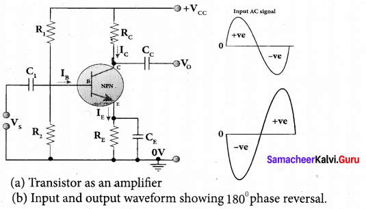
To start with, the Q point or the operating point of the transistor is fixed so as to get the maximum signal swing at the output (neither towards saturation point nor towards cut-off). A load resistance, Rc is connected in series with the collector circuit to measure the output voltage. The capacitor C1 allows only the ac signal to pass through. The emitter bypass capacitor CE provides a low reactance path to the amplified ac signal. The coupling capacitor Cc is used to couple one stage of the amplifier with the next stage while constructing multistage amplifiers. Vs is the sinusoidal input signal source applied across the base-emitter. The output is taken across the collector-emitter.

Applying Kirchhoff ’s voltage law in the output loop, the collector-emitter voltage is given by
VCE = VCC – IC RC
Working of the amplifier:
During the positive half cycle
Input signal (Vs) increases the forward voltage across the emitter-base. As a result, the base current (IB) increases. Consequently, the collector current (IC) increases p times. This increases the voltage drop across RC which in mm decreases the collector-emitter voltage (VCE). Therefore, the input signal in the positive direction produces an amplified signal in the negative direction at the output. Hence, the output signal is reversed by 180° as shown in figure (b).
During the negative half cycle
Input signal (Vs) decreases the forward voltage across the emitter-base. As a result, base current (IB) decreases and in turn increases the collector current (IC). The increase in collector current (IC) decreases the potential drop across Rc and increases the collector-emitter voltage ( VCE). Thus, the input signal in the negative direction produces an amplified signal in the positive direction at the output. Therefore, 180° phase reversal is observed during the negative half cycle of the input signal.
![]()
[OR]
Question 38.
(b) Explain the three modes of propagation of electromagnetic waves through space.
Answer:
Propagation of electromagnetic waves:
The electromagnetic wave transmitted by the transmitter travels in three different modes to reach the receiver according to its frequency range:
1. Ground wave propagation (or) surface wave propagation (nearly 2 kHz to 2 MHz)
2. Sky wave propagation (or) ionospheric propagation (nearly 3 MHz to 30 MHz)
3. Space wave propagation (nearly 30 MHz to 400 GHz)
1. Ground wave propagation:
If the electromagnetic waves transmitted by the transmitter glide over the surface of the earth to reach the receiver, then the propagation is called ground wave propagation. The corresponding waves are called ground waves or surface waves.
Both transmitting and receiving antennas must be close to the earth. The size of the antenna plays a major role in deciding the efficiency of the radiation of signals. During transmission, the electrical signals are attenuated over a distance. Some reasons for attenuation are as follows:
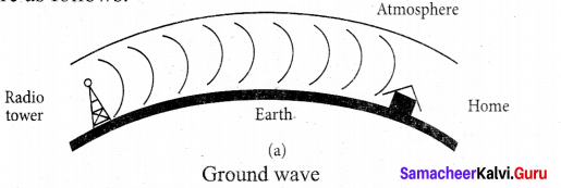
Increasing distance: The attenuation of the signal depends on
- power of the transmitter
- frequency of the transmitter, and
- condition of the earth surface.
Absorption of energy by the Earth: When the transmitted signal in the form of EM wave is in contact with the Earth, it induces charges in the Earth and constitutes a current. Due to this, the earth behaves like a leaky capacitor which leads to the attenuation of the wave.
Tilting of the wave: As the wave progresses, the wavefront starts gradually tilting according to the curvature of the Earth. This increase in the ti It decreases the electric field strength of the wave. Finally, at some distance, the surface wave dies out due to energy loss.
The frequency of the ground waves is mostly less than 2 MHz as high frequency waves undergo more absorption of energy at the earth’s atmosphere. The medium wave signals received during the day time use surface wave propagation.
It is mainly used in local broadcasting, radio navigation, for ship-to-ship, ship-to-shore communication and mobile communication.
2. Sky Wave Propagation:
The mode of propagation in which the electromagnetic waves radiated from an antenna, directed upwards at large angles gets reflected by the ionosphere back to earth is called sky wave propagation or ionospheric propagation. The corresponding waves are called sky waves.
The frequency range of EM waves in this mode of propagation is 3 to 30 MHz. EM waves of frequency more than 30 MHz can easily penetrate through the ionosphere and does not undergo reflection. It is used for short wave broadcast services. Medium and high frequencies are for long-distance radio communication. Extremely long distance communication is also possible as the radio waves can undergo multiple reflections between the earth and the ionosphere. A single reflection helps the radio waves to travel a distance of approximately 4000 km.
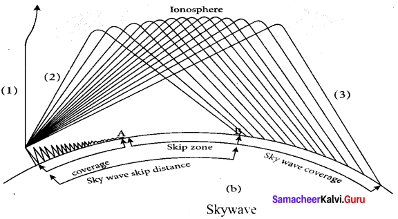
Ionosphere acts as a reflecting surface. It is at a distance of approximately 50 km and spreads up to 400 km above the Earth surface. Due to the absorption of ultraviolet rays, cosmic ray, and other high energy radiations like a, p rays from sun, the air molecules in the ionosphere get ionized. This produces charged ions and these ions provide a reflecting medium for the reflection of radio waves or communication waves back to earth within the permitted frequency range. The phenomenon of bending the radio waves back to earth is nothing but the total internal reflection.
3. Space wave propagation:
The process of sending and receiving information signal through space is called space wave communication. The electromagnetic waves of very high frequencies above 30 MHz are called as space waves. These waves travel in a straight line from the transmitter to the receiver. Hence, it is used for a line of sight communication (LOS).
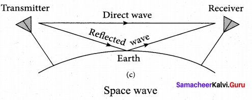
For high frequencies, the transmission towers must be high enough so that the transmitted and received signals (direct waves) will not encounter the curvature of the earth and hence travel with less attenuation and loss of signal strength. Certain waves reach the receiver after getting reflected from the ground.